
Network Questions Covering Routing, Gateways, Protocols, and SNMP MIB Structure
1. An IP network is connected to a Novel IPX network via a gateway. The IP network protocol stack includes the following layers: TCP, IP, 802.3, and Physical Layer. The IPX network protocol stack includes: TCP, IPX, 802.3, and Physical Layer. Draw and explain the protocol layers of the IP network, the gateway and the IPX network.
TCP/IP and the Novel IPX/SPX protocols are both routable however use different mechanisms to establish communication sessions at OSI layer 4, different formats to establish logical addressing at OSI layer 3, different frame types for local network forwarding at OSI layer 2 and, depending upon the type of network infrastructure and OSI layer 2 protocols used, may even use different network media (cable types) on OSI layer 1. First, the TCP/IP OSI layer 4 TCP protocol is a reliable protocol that uses a three way handshake to establish a session with the system to which it is sending and receiving data. The handshake starts with a Syn packet, and the response is a Syn Ack packet, which is followed by an Ack packet to establish the session. The gateway translates this handshake to and from the system using IPX by translating the TCP handshake to the equivalent SPX handshake and vice versa. Then at the OSI layer 3 the IP protocol manages logical addressing and routing using IP addresses that consist of 32 bits binary which humans view in four octets of dotted decimal notation. IPX is a routable protocol just like IP however, the addresses longer and consist of the layer 2 hardware MAC address and a network address or number. When IPX sends a data packet to the gateway the gateway translates the packet, including source and destination to the source and destination IP addresses. Since both IPX and IP are connectionless, no handshaking is involved at this layer. At the OSI layer 2 there are major differences in frame types even though both use the same type of addressing type (hardware or MAC addresses). So the gateway must respond to ARP requests to and from the TCP/IP system to provide the IP address that is assigned to the IPX system and handled in the gateway. The gateway does not have to handle ARP on the IPX side because IPX already contains the MAC address of the source and destination in the IPX addresses. The gateway must also translate between the commonly used Ethernet II frame on the TCP/IP system to the 802.3 (raw) frame used on the IPX system because frames differ substantially with a large amount of header data in the 802.3 frames not implemented in the Ethernet II frames. The gateway may also have to handle physical layer differences such as CAT 6 on the TCP/IP side and IBM Token Ring cables (IBM type 1, 2, or 3 cables) on the other which have been commonly used in IPX/SPX Token Ring networks.
![]()
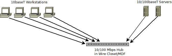
2. Design a client/server network with two servers operating at 100Base-T Fast Ethernet speed and the clients operating at regular 10Base-T Ethernet speed using a 10/100 Mbps NIC. The hub is located in a wiring closet, but the servers and clients are not. Assume that a satisfactory performance is achieved at 30% utilization of the LAN.
This network design used a physical Star topology and a logical bus because a hub is implemented as a requirement (rather than a switch) so that the network shares a single collision domain amongst all the devices on the network. Each server and workstation is connected to the network using a CAT 5 UTP cable that supports both 10 and 100 Mbps and is no more than 100 meters in length. Since a hub is deployed for this network, all systems use half-duplex connections (rather than full duplex) which helps to avoid collisions on the single collision domain network. In order for the workstations to operate at 10 Mbps, the NIC on each workstation must be forced to operate at 10 Mbps (because they are 10/100 Mbps NICs). The workstations should also be forced to operate at half-duplex to decrease possible collisions on the network and increase throughput. By deploying the workstations at 10 Mbps and configured for half-duplex, and given that the servers support 100 Mbps, 30 % or more network utilization (30 Mbps) can be maintained.
3. Write an ASN.1 module that specifies DaysOfWeek as a SEQUENCE type with each day of the week (day1, day2,…) as the type VisibleString. Write the ASN.1 description:
a) for the structure
- ASN.1 Structure:DaysOfWeek ::= SEQUENCE {
day1 VisibleString
day2 VisibleString
day3 VisibleString
day4 VisibleString
day5 VisibleString
day6 VisibleString
day7 VisibleString
b) for the value.
ASN.1 record value:
day1 “Sunday”
day2 “Monday”
day3 “Tuesday”
day4 “Wednesday”
day5 “Thursday”
day6 “Friday”
day7 “Saturday”
4. TCP is a connection-oriented protocol and UDP is a connectionless protocol. Identify the differences in the two MIBs that exemplify this difference.
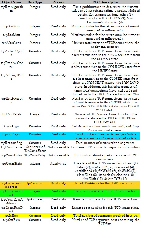
The difference between the MIB II entries for UDP and TCP is substantial because TCP is connection oriented. This means that TCP tracks the status of each segment of data sent and received whereas UDP just sends and receives without managing each session. Below is a list of the features in the TCP and UDP MIB II entries. The entries that are similar are highlighted with the same color for TCP and UDP entries. So aside from those features that are similar, the vast majority of entries, especially TCP entries are entirely different. For example, TCPinSeg, and UDPinDatagrams are similar as both count the number of data packets received. UDPinErrs and TCPinErrs (highlighted in yellow) are also similar as they too are counter status measurements. However, anything that deals with the connection oriented capabilities of TCP are different and the connectionless features of UDP are different. UDPnoPorts measures the number of datagrams received where there was no listening port specified. This measurement is not valid in TCP because TCP, being connection oriented, establishes a socket that includes both an IP address and a port number to establish the connection and communicate. TCPActiveOpens, TCPPassiveOpens, and TCPAttemptFailed are all counters that would not be seen in UDP because they involve status of a TCP session connection.
Exhibit 1: UDP MIB II Entries
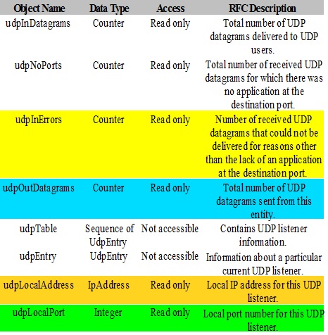
Exhibit 2: TCP MIB II Entries:
Leave a Reply